Group: Sam Mitchell, Emma Mallen, Rhob Edwards, Andrew Sutherland and Ellie Hewitt.
About Rapid Prototyping
Rapid prototyping is the use of computer controlled machines to produce prototypes quickly and accurately. CAD software such as Solidworks or AutoCAD are used to product computer models of the intended product, these files can then be exported into files compatible with that of the rapid prototyping machines. The models are manufactured with the use of a machine that uses additive layer manufacturing technology. There were three different rapid prototyping machines available for our group to use for this project. This includes the MakerBot Replicator 2, the Objet 24/ 30 and the Z-corp printer. We took advantage of the use of the MakerBot to produce a rough test model before looking towards the objet to produce the test and final
prototype. We chose not to use the Z-corp printer due to the material that it uses has a similar finish to plaster so it is brittle and easily broken.
prototype. We chose not to use the Z-corp printer due to the material that it uses has a similar finish to plaster so it is brittle and easily broken.
MakerBot
The MakerBot allows the production of a CAD design into a 3D solid model through the use of the material PLA. The MakerBot provides a realistic model of the product designed on a CAD program such as Solidworks. The files on Solidworks need to be converted to a format which is compatible with the MakerBot desktop software, ‘.stl’ is an example of one of these accepted formats. The MakerBot Desktop software allows you to the parts on the bed, scale the parts to a suitable size and provides a preview of how the product will print showing the print head transitions and layer by layer construction. This software will also give an estimated build time. The software changes the stereolithography files into instructions so the MakerBot understands where to build and where not to extrude material. The MakerBot machine accepts SD cards and direct computer connection through the use of a standard USB cable, these are both methods of sending the data to print.
When the MakerBot has received the file and set to print, the PLA is heated up to 230◦C and the molten PLA is extruded through the nozzle. A raft can be built as a foundation to build upon, it also aids with the removal of the final product from the MakerBot bed. The software generates a support structure, this is to ensure that parts that involve overhangs and geometry similar are able to be printed. This machine uses the same material for both the build and the supports, this makes them somewhat difficult to separate. MakerBot’s reduce material consumption by constructing the parts using a patterned infill as opposed to a solid block of material, the default infill is a honeycomb pattern however this can be modified.
When the MakerBot has received the file and set to print, the PLA is heated up to 230◦C and the molten PLA is extruded through the nozzle. A raft can be built as a foundation to build upon, it also aids with the removal of the final product from the MakerBot bed. The software generates a support structure, this is to ensure that parts that involve overhangs and geometry similar are able to be printed. This machine uses the same material for both the build and the supports, this makes them somewhat difficult to separate. MakerBot’s reduce material consumption by constructing the parts using a patterned infill as opposed to a solid block of material, the default infill is a honeycomb pattern however this can be modified.
Objet 30
A more advanced and accurate prototyping machine was available for use, the Objet 30. A varied model was also available, an Objet 24, however the Objet 30 provides a larger bed size of “300 x 200 x 150mm (Series, 2014)”. The machine constructs a 3D product out of a rigid opaque photopolymer, though other materials are available. Operation of the Objet printer is similar to the MakerBot, both utilising STL files from software packages such as Solidworks to construct a 3D model through a process of stereolithography. The Objet printers use the Objet Studios software package in conjunction with a valid STL file to manufacture a 3D model. The Objet Studios package provides a preview of the STL file prior to printing, while allowing the user to map support structures of “FullCure® 705 non-toxic gel-like photopolymer support” (Series, 2014). Furthermore, the software provides estimated build times and material usage. During the process of manipulating build parameters, alternate building materials may also be set. Support material used is impregnated with build material during the manufacture process, improving structural rigidity to reduce failures during a build. Support material may be removed after completion via a pressurized water jet.
Advantages of Rapid Prototyping
• It allows designers to interact with a physical representation of their concept.
• The design of a product can be better communicated to a client through the use of a prototype.
• There is no need for moulds or patterns to be manufactured before the product can be produced reducing on expenditure.
• Craftsmen are not required to the same degree vastly reducing the labour costs to manufacture the part.
• It is an additive process meaning less waste material is created.
• They can make very complex geometry’s with very small tolerances that are otherwise difficult/not possible to produce in one piece or with one sole manufacturing method.
• Allows for the inspection of a design prior to mass manufacture.
• There are more and more materials becoming available with rapid prototyping machines ranging from polymers to titanium.
• Multiple iterations of one design can be saved and referred back to and prototyped again.
Disadvantages of Rapid Prototyping
• Testing stress, thermal and fluid dynamics prior to production reducing the probability of structural failures.
• For mass production a user can simulate potential manufacturing processes. This can aid in assessing the most suitable manufacturing techniques.
• Allows design changes to be made depending on testing results. For example, tests exploring the aerodynamics of a toy helicopter propeller may indicate changes that are necessary for sufficient lift.
• Simulations may reduce the probability of failure post-production and save costs.
• Allows a user to understand product limitations that may be suitable for design changes. Allows for multiple saved variations of a design for referencing and testing.
• Explore how a concept performs mechanical tasks prior to production.
Benefits of Computer Aided Engineering (CAE)
Computer aided engineering uses software to simulate conceptual performance, allowing the user to make modifications to improve potential product performance (Limited, 2016). Benefits of such software include:
• Testing stress, thermal and fluid dynamics prior to production reducing the probability of structural failures.
• For mass production a user can simulate potential manufacturing processes. This can aid in assessing the most suitable manufacturing techniques.
• Allows design changes to be made depending on testing results. For example, tests exploring the aerodynamics of a toy helicopter propeller may indicate changes that are necessary for sufficient lift.
• Simulations may reduce the probability of failure post-production and save costs.
• Allows a user to understand product limitations that may be suitable for design changes. Allows for multiple saved variations of a design for referencing and testing.
• Explore how a concept performs mechanical tasks prior to production.
• For mass production a user can simulate potential manufacturing processes. This can aid in assessing the most suitable manufacturing techniques.
• Allows design changes to be made depending on testing results. For example, tests exploring the aerodynamics of a toy helicopter propeller may indicate changes that are necessary for sufficient lift.
• Simulations may reduce the probability of failure post-production and save costs.
• Allows a user to understand product limitations that may be suitable for design changes. Allows for multiple saved variations of a design for referencing and testing.
• Explore how a concept performs mechanical tasks prior to production.
Materials Selection
Objet30
The material used by the Objet30 printer available was an Opaque Rigid Photopolymer - This material choice affords a number of benefits. The material has good dimensional stability while being able to provide a fine detail with added options to simulate the appearance of production parts, these advantages aiding the material in suitability for rapid tooling. Continuing on its beneficial qualities, the material can provide easy to remove support material and has access to soluble support material. Moreover, the material is available in a variety of colours.
A major disadvantage to this material selection is its expensive cost. Furthermore, the material reacts poorly to solvents and chemicals which can warp and dissolve the structure of an object. The material is also brittle under heavy loads and exhibits a weaker impact strength compared to engineered polymer plastics.
A major disadvantage to this material selection is its expensive cost. Furthermore, the material reacts poorly to solvents and chemicals which can warp and dissolve the structure of an object. The material is also brittle under heavy loads and exhibits a weaker impact strength compared to engineered polymer plastics.
MakerBot
The resin used by the MakerBot printer available was PLA (Polylactic Acid) - This material is rigid, affords low warping of parts, relatively good tensile strength and has high mechanical stability, all while remaining accurate and being a low cost material. The material can also be found in a number of colours and is biodegradable.
While being a stable material, PLA also presents disadvantages. PLA can react with water at high temperatures and undergo de-polymerization and has high water permeability. The material also exhibits a very low impact strength coupled with low maximum service and heat deflection temperatures. (Anon., n.d.) (Pandey, 2014)
(Anon., 2011)
Adaptations Made to Original Design


Adaptations - Original Design to MakerBot Design
As the original design for the Radial Engine was complicated and quite large, modifications to the design were implemented.
Removing the ‘injectors’ to simplify the design, with the removal of the ‘injectors’ the casing around these components could also be reduced to cut down on unnecessary material costs. Tolerances were added in for the pins that hold together the articulating rods and piston heads by the removal of surrounding material. The articulating rods were then resized to accommodate the tolerance between them and the master rod and between the rods themselves and the piston heads. The 0.2mm clearance between the counter weight and the master rod was formed. The diameter of the pin that connects the master rod and the counter weight together was increased this was to ensure the part wouldn’t be too thin as this could lead to the failure of the part whilst removing the support material or during the use of the item. The required tolerance of the pin that connects to the master rod and the counter weight together was created and confirmed. Some detail was then removed from the counter weight to allow tolerances for itself and the casing and to save on material costs. The casing was scaled up to allow for tolerances between itself and the piston heads among other parts. A new part made was the propeller. The propeller was added to guarantee the Radial Engine could manually turn. The casing was further edited by the addition of viewing windows. The windows allowed for viewing of the internal components.
Removing the ‘injectors’ to simplify the design, with the removal of the ‘injectors’ the casing around these components could also be reduced to cut down on unnecessary material costs. Tolerances were added in for the pins that hold together the articulating rods and piston heads by the removal of surrounding material. The articulating rods were then resized to accommodate the tolerance between them and the master rod and between the rods themselves and the piston heads. The 0.2mm clearance between the counter weight and the master rod was formed. The diameter of the pin that connects the master rod and the counter weight together was increased this was to ensure the part wouldn’t be too thin as this could lead to the failure of the part whilst removing the support material or during the use of the item. The required tolerance of the pin that connects to the master rod and the counter weight together was created and confirmed. Some detail was then removed from the counter weight to allow tolerances for itself and the casing and to save on material costs. The casing was scaled up to allow for tolerances between itself and the piston heads among other parts. A new part made was the propeller. The propeller was added to guarantee the Radial Engine could manually turn. The casing was further edited by the addition of viewing windows. The windows allowed for viewing of the internal components.


MakerBot Prototype
The first prototype designed was built in the MakerBot, this was to confirm there were no errors in the overall Solidworks design. This prototype did not affect our budget as these machines are ‘free to use’, this allowed the full budget to remain dedicated to the test and final prints on the Objet 30. We also had to take into consideration that the ‘Objet 30’ machine required a 0.2mm tolerance between moving parts. This allows for a spacing between parts so that they are free to move, preventing the manufacture of a defective prototype.
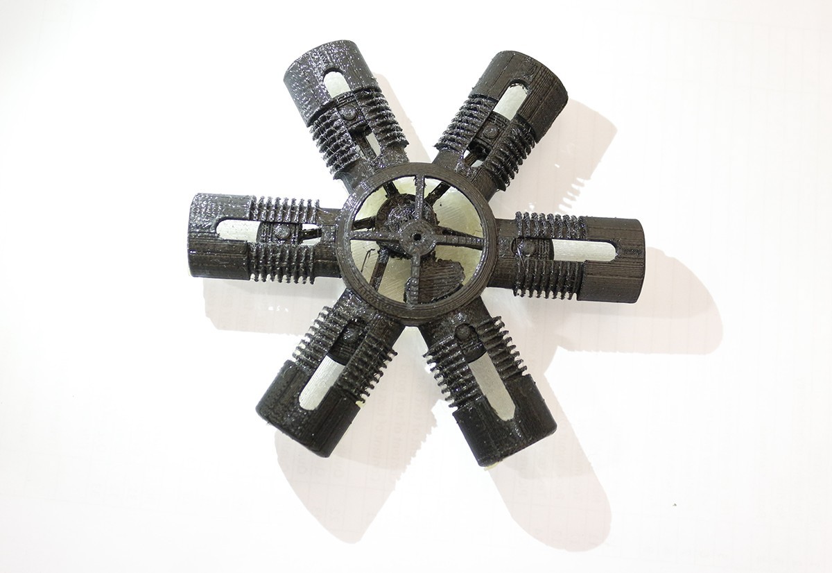
This version was separated into three key component parts and two minor parts. However, the support material proved difficult to remove (due to it being manufactured from the same material as that of the build material) resulting in the mechanism being unable to operate. An issue with the bottom casing was also incurred, this resulted in a poor print. We found that this was in fact a misprint and there was no error in the CAD file. Once the support material was removed the prototype was assembled, the mechanism was placed inside the casing and the case halves were glued together. A hot glue gun was used to make up for space between the case halves caused by the misprint of the bottom case half resulting in the loss of layers. The minor parts being the propeller and a pin were also broken in the attempt at removing them from the raft and support material.
This version was separated into three key component parts and two minor parts. However, the support material proved difficult to remove (due to it being manufactured from the same material as that of the build material) resulting in the mechanism being unable to operate. An issue with the bottom casing was also incurred, this resulted in a poor print. We found that this was in fact a misprint and there was no error in the CAD file. Once the support material was removed the prototype was assembled, the mechanism was placed inside the casing and the case halves were glued together. A hot glue gun was used to make up for space between the case halves caused by the misprint of the bottom case half resulting in the loss of layers. The minor parts being the propeller and a pin were also broken in the attempt at removing them from the raft and support material.
MakerBot - Prototype 08/03/16
4.5 hours Mechanism & Top casing 2 Parts
2.5 Hours Bottom Casing 1 Part


Adaptations - MakerBot Design to Objet 30 Test Prototype Design
We were happy with the overall design of the model after being able to inspect it further using the ‘MakerBot’ manufactured prototype. So at its current scale it was priced up to be prototyped using the ‘Objet 30’. This manufacturing price was estimated at £65.91, this was already over budget and would not allow for the prototyping of a test prior to final artefact.
Due to the design being above the set budget, it was re-evaluated and excess materials were removed in an attempt to lower the cost of the prototype to within the set budget. This was done primarily by the reduction of the cylinders. After these alterations the prototype was priced up at £39.12.
It was decided that it would not be worth the risk to attempt one print with the majority of the budget. The model then underwent further changes more alterations were needed to be made before we did the prototype print in the ‘Objet 30’ to lower the price further. In Solidworks the overall design was resized by scaling it down by a factor of 0.75. Throughout the modifications it was made certain that all the tolerances on the design were 0.2mm and that none of the alterations to the designs conflicted with this as scaling the whole model also reduced the tolerance between the parts.


Objet 30 Test Prototype
When retrieving the prototype from the ‘Objet 30’ it is then pressure washed to remove the support material. During the pressure wash the technician accidentally broke the propeller off the model. Then he increased the pressure again to try to remove further support material that was trapped inside the casing and damaged some internal components. The support material proved to be difficult to remove from the cylinders using the jet washer so to prevent further damage to the model it was removed by hand using an array of tools.
Objet 30 - Prototype 14/03/16
5.5 Hours Full CAD Model 1 Part £17.76


Adaptations - Objet 30 Test Prototype Design to Objet 30 Final Prototype Design
As the next print would be the final model. Amendments were made once again to prepare for the final print. The holes were added as a case adaptation to cylinders, this was to allow the removal of the support material from inside the cylinders and around the piston heads. We then increased thickness of propeller to make it more resilient. The diameter of the master rod pin, propeller pin and supporting pin where changed to an increased size for added durability. With the adaptation of the pins all hole effected by this also had diameters increased to ensure a 0.2mm tolerance where required. The whole design of the counter weight was changed to ensure there was adequate material around the centre hole once again to ensure durability. Finally, the Radial Engine was increased by a scale factor of 1.5 then was reduced by a factor of 0.8.
Renders of Final CAD Model


Final CAD Animation
Objet 30 Final Prototype
To prevent damaged to the model that we experienced during the test print whilst removing support material, it was decided that the model should not be jet washed and instead the support material was to be removed by hand using a series of tools. Once all support material was removed the prototype functioned correctly. Our final prototype was a success and we were left with only £0.68 of our budget meaning almost all funds were utilised.
Objet 30 - Final Prototype 15/03/16
5 Hours Full CAD Model 1 Part £31.56
Video of the Objet 30 Final Prototype


Technical Drawing of Half Cylinder with Window Part

Technical Drawing of Radial Engine Assembly

Critical Analysis
Successful aspects of the project
Overall, we believe that the group completed the assignment brief successfully. We selected the design forwarded by Sam Mitchell, believing it to be the most complex and challenging. Throughout the assignment the 3D model adapted to a number of set limitations, two primary limitations focussing on a restrictive budget as well as the facilities available. Although, the limitations provided key opportunities for the group to learn new manufacturing techniques and gather a greater understanding of rapid prototyping processes.
Problems encountered
The limited outlined budget of £50 set in the brief produced problems during the closing stages of the assignment. Moreover, an early prototype manufactured using the provided MakerBot facilities produced a miss print that was out of our control.
Things what we would change if we were to repeat the process
If the assignment were to be repeated, we would allocate a better distribution of the CAD workload. As Sam’s design was forwarded, it was clear that he would have a greater in-depth understanding of the model compared to other members of the group. Due to this consideration, and the limited time frame to complete the assignment, it was discussed that it would be more efficient for Sam to undertake most CAD related tasks. Unfortunately, this resulted in a large portion of time intensive work being dedicated towards one group member. Another possible change would be to the assigned budget for the task. A larger budget would allow for a number of prototypes to better understand the limitations of our design, and potentially provide a platform for a more complex finished product.
How we have worked together as a team
The team worked well together with no disputes to cause issue, this simplified meetings aiding productivity. To the best of our ability work was fairly distributed, however unfortunate exceptions were discussed and made for the CAD workload whereby the work was completed by Sam. Despite this, other group members provided useful additions to the assignment wherever possible. Employing a system of regular group meetings aided in our ability to assign tasks and progress through the assignment.
Conclusion on the 3D Printing
We found our progression through the assignment to be successful in delivering positive learning outcomes while under working limitations. We achieved all goals set while producing two prototypes and a final product, all within the £50 manufacturing budget.
Future Adaptations
Design Limitations
Many initial properties and components of the original radial engine were evaluated and edited to satisfy the manufacturing limitations in the equipment available. Moreover, our project brief furthered design limitations by stipulating that a finite budget of £50 for the manufacturing process, while also stating that the product must be manufactured in one stage - sent to the Objet30 as one part.
These limitations drastically impact the size and scale of the object manufactured.
Creative Additions and Revisions
A primary adaptation discussed would be the reuse of original design concepts used in the initial radial engine design. The reintroduction of fuel injectors and spring components would aid in the functional qualities of the finished product if we were to adapt it further. To continue a theme of realistic design considerations, discussions have also been made suggesting an introduction of additional peripheral components to the engine block. This could include the addition of inlet and outlet ports, as well as tubing to allow the necessary distribution of air and fuel flow for the engine to function effectively.
Based on difficulties encountered related to the cleaning and removal of support material around the engine, basic developments could be made to the overall design of the prop shaft and accompanying propeller. As we worked with a limited budget towards manufacturing, limited design and materials were dedicated to the propeller. This created a relatively weak propeller section that could be easily damaged by the use of high pressure water jets (typically used in the removal of support material after printing with the provided Objet30 printer). Revising the propeller section to be more resistant to cleaning processes would greatly improve the probability of a successful final result, with operational moving parts. Furthermore, the basic visual design of the propeller could be enhanced to support a more representative size as well as increased complexity.
Based on difficulties encountered related to the cleaning and removal of support material around the engine, basic developments could be made to the overall design of the prop shaft and accompanying propeller. As we worked with a limited budget towards manufacturing, limited design and materials were dedicated to the propeller. This created a relatively weak propeller section that could be easily damaged by the use of high pressure water jets (typically used in the removal of support material after printing with the provided Objet30 printer). Revising the propeller section to be more resistant to cleaning processes would greatly improve the probability of a successful final result, with operational moving parts. Furthermore, the basic visual design of the propeller could be enhanced to support a more representative size as well as increased complexity.
Manufacturing Process
Future adaptations would benefit greatly from an increased budget to allow more liberal use of materials for the manufacturing of larger scale products, in this case the radial engine. Increased usage of material would aid in the overall structural integrity of the finished work providing a more stable platform for support removal and cleaning.
Support structure removal and cleaning provided the most difficulties over the course of the project. For the radial engine to work effectively all the support material is required to be removed from the internal mechanism, however the process of removing the support material can break delicate internal components. This process could be adapted by use of water-soluble support material. Using such a material reduces the impact of the support removal process and alleviates concerns related to delicate sections or components.
A separate solution and adaptation would be the manufacturing of components and sections separately, as opposed to a single part. This manufacturing process would benefit the basic manufacturing of each section and allows for more accurate and effective support material removing while using the facilities available.
Materials Selection
In an attempt to produce a more realistic representation of an engine, while also providing a more stable working platform for a potential working engine, a development could be made to use a metal-based rapid prototyping machine. An example of this technology could be the Renishaw AM250 (Renishaw, 2016). This could benefit the engine block and internal components by adding a greater tolerance to forces and pressure changes associated with a working engine.
Distribution of work
Sam Mitchell
I created all the CAD models and the animation using Solidworks and created the photorealistic rendered images using KeyShot 5 software. I also used the MakerBot desktop software to create the required build files for the first prototype. I met with the technician’s multiple times for the costing of different versions of the model to ensure that the model created would be within the budget and allow for multiple attempts. I also removed by hand the support material involved with the final prototype to prevent the high pressure water jet damaging any fragile components. With the assistance from Emma we formatted and compiled the different sections of the report. I also collaborated with Rhob in reading and rewording the sections completed by my fellow team members to ensure the report flowed with the use of a similar language style throughout. Finally, I prepared the final presentation to be delivered by my group.
Emma Mallen
Throughout the project I have contributed to several aspects of the project including the organisation of the group meetings, documentations of each meetings and making requests for group members to complete tasks that I assigned to them. I also separating the report into specific sections, and participated into the documentation of the report and I will be taking part in the presentation of the project. The areas I then composed in the report were the; Adaptations made to original design and the Critical Analysis. Overall I believe we worked well together as a group and I am pleased with the overall result.
Rhob Edwards
During the course of the project I contributed to a number of areas related to the manufacture, documentation and possible adaptations to a potential future model. I contributed initially within group discussions to assess the legitimacy and possibility of CAD designs for a successful project. Before the manufacturing stages of the project I undertook research to explore the limitations of each of the manufacturing methods we proposed so that considerations could be made in advance. I later helped in managing a MakerBot manufacturing process for an early prototype to explore the problems that may have been associated with the CAD modelling produced. After each of the manufacturing processes I then documented the prototypes and final models for review and evaluation. Lastly, I wrote up the page exploring future adaptations for the project and modelling. Beyond the completion of the written report, I then contributed in the presentation of work.
Ellie Hewitt
Throughout the project I have contributed in several different parts including the documentation, printing the 3D model and I will be presenting the project at a later date. To begin with I was involved in separating the work into everyone’s specific areas. I then participated in setting up the MakerBot machine ready for our first the first initial print of the radial engine so we could understand how the model would turn out and identify any problems we would encounter printing the final model. The areas I then wrote in the report were the introduction, MakerBot and Objet 30 and I will be taking part in the presentation that will be given. Overall I believe we worked well together as a group in making sure the completion of the project was on time.
Andrew Sutherland
My parts of the group project included getting the information from the technician that was required before the modifications were made to the existing CAD model such as the tolerances needed for the moving sections. I also wrote the introduction for rapid prototyping, the advantages section and the disadvantages section of rapid prototyping. Benefits of computer aided engineering was another section that I completed. Overall I believe that the group as a whole utilised each other's skills fully and everyone fully participated in the project throughout.
References
Anon., 2011. Pros and Cons of Acrylic Resin. [Online]
Available at: http://www.doityourself.com/stry/pros-and-cons-of-acrylic-resin#b
[Accessed 16 March 2016].
Anon., n.d. CES Edupack 2015, s.l.: Granta Design Limited.
Limited, S. I. S., 2016. Siemens PLM Software. [Online]
Available at: http://m.plm.automation.siemens.com/en_gb/plm/cae.shtml
[Accessed 15 March 2016].
Pandey, R., 2014. Photopolymers in 3D printing applications. [Online]
Available at: https://www.theseus.fi/bitstream/handle/10024/80083/pandey_ramji.pdf?sequence=1 [Accessed 16 March 2016].
Renishaw, 2016. AM250. [Online]
Available at: http://www.renishaw.com/en/am250--15253
[Accessed 16 March 2016].
Series, S. D., 2014. The ultimate in professional desktop 3D printing. [Online]
Available at: http://www.stratasys.com/3d-printers/design-
series/precision/~/media/AECD02CC265143198CD493D1664EEF55.ashx
[Accessed 16 March 2016].
